In precision injection molding, sink marks are a common problem; they hurt parts quality also affect both looks and strength.
With new digital tools, Moldflow analysis has become a strong solution. It simulates material flow, cooling, and shrinkage. This helps predict and improve process parameters. This blog explores how moldflow simulation finds injection molding defects at their root.

What Are Sink Marks?
Sink marks, also known as dents or shrink marks, are common defects in the injection molding process. They happen due to uneven material shrinkage while cooling.
These depressions on the surface of the part often appear in thick-walled sections, like ribs and bosses. They can also appear in areas far from gates. This happens when cooling time and mold temperatures do not match.
What Causes Sink Marks in Injection Molding?
Mold Design & Process Flaws
Poor control of mold temperatures or cooling layouts.
Incorrect injection speed and pressure causing incomplete filling of the mold cavity.
Short shots due to low melt flow or premature freezing.
Part Design Issues
Non-uniform part geometry (e.g., abrupt wall thickness changes).
Sharp corners create weld lines or stress points.
Plastic Material Selection
High-shrinkage plastics (e.g., PP, nylon) with unstable melt temperatures.
Poor flow of molten plastic due to viscosity mismatches.
How Do Mold Designers Prevent Sink Marks?
Stage 1: Design for Manufacturing (DFM) Review
Before Moldflow analyzing, mold designers conduct a Design for Manufacturing (DFM) review to:
- Identify high-risk areas (e.g., thick sections, sharp transitions).
- Propose geometry adjustments (e.g., uniform wall thickness, radii ≥0.5× nominal wall thickness).
- Optimize gate locations to ensure balanced filling and minimize weld lines.
Stage 2: Moldflow Analysis Sink Mark Solutions
Predict Flow & Cooling Risks
- Visualize pressure in the mold cavity to avoid vacuum voids.
- Map mold temperatures to balance cooling in thick sections.
Optimize Part & Mold Design
- Adjust part geometry (e.g., uniform wall thickness, radii ≥0.5T).
- Redesign gates to eliminate weld lines and ensure full cavity filling.
Validate Process Parameters
- Test injection speed and pressure combinations to prevent short shots.
- Calculate ideal hold time and cooling time to minimize shrinkage.
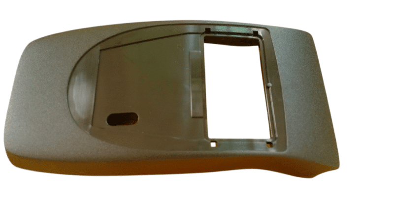
Case Study:
Medical Device with Sink Marks
Problem: Sink marks near thick ribs in ABS case.
DFM Optimization:
Both sides of the case are inner with ribs, and the average wall thickness is too thick.
High potential risk of sink marks in that area:
We added a crater at the mold core side to avoid sink marks.


Parts With Sink Marks
Problem: Sink marks near thick ribs in a PA6-GF30 bracket.
Moldflow Insights:
Uneven cooling and excessive material in thick sections.
Premature gate freeze-off due to low hold time.
Solutions:
Reduced rib thickness by 40% and added cooling channels.
Adjusted injection speed and increased mold temperature.
Result: Zero sink marks; 15% lighter part weight.
Best Practices For Sink Mark Prevention
Part Design
- Make sure that wall thicknesses are uniform and try to avoid large variations in wall thickness. Avoid thick ribs; use thin-walled sections (ribs ≤1/3 base thickness).
- Add radii (R≥0.5T) to corners to reduce stress.
Mold & Process
- Place cooling channels near thick areas to regulate mold temperatures.
- Optimize injection speed and pressure for balanced filling.
Material Selection
- Choose low-shrinkage resins (e.g., ABS, PC).
- Use filled and reinforced material(e.g., GF30) for stability.
Conclusion
Sink marks in injection molded parts stem from poor part geometry, material selection, and processing parameters. Moldflow analysis provides data-driven solutions to eliminate defects, optimize cooling time, and ensure flawless production.
Need Expert Help?
Contact us for a free Moldflow consultation to fix sink marks before your mold starts the tooling process.