Design for Manufacturing (DFM) Principles:
A Guide to Streamlining Production
What is Design for Manufacturing (DFM)?
Design for Manufacturing (DFM) is a systematic approach that involves considering the manufacturing of a product during its design phase. It encompasses various aspects such as material selection, ease of assembly, tooling requirements, and the overall production process. By applying design for manufacturing (DFM) principles into the design process, manufacturers can identify and address potential issues before production begins. This can save money, prevent costly fixes, and lower the chances of product failure.
The importance of Design For Manufacturing( DFM) Principles
DFM is particularly important in processes like injection molding and CNC machining. By using DFM principles early on, companies can save time and money, and make production smoother. This also improves the overall quality of the product.
Collaboration in DFM
An effective Design for Manufacturing (DFM) approach involves everyone, including manufacturers, engineers, suppliers, and designers. By working together, we can address all requirements and plan effectively, leading to smoother production and better-quality products.
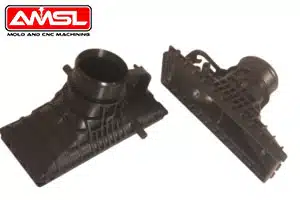
What are the five principles of Design for Manufacturing (DFM)?
1. Process: Choosing the appropriate manufacturing process is key to cost-effective production. Consider tolerances and material requirements for each component.

EDM-workshop2. Design: Intricate designs can escalate production, usage, and maintenance costs. Therefore designs should adhere to production standards and specify details like thickness, tolerance, texture, and consistency.
3. Materials: Selecting materials early saves time and money. Consequently, factors such as steel hardness, machinability, strength, wear resistance, thermal stability, and ease of machining need to be considered.
4. Environment: It’s essential to develop each product component to suit its operating environment. By doing so, you ensure that the product performs reliably under specific conditions.
5. Testing: Thorough testing is critical to ensure product quality and compliance with industry standards. As a result, it helps in identifying potential issues before the product goes into full production.
How does Design For Manufacturing( DFM) Principles Impact the Service Life of Mold?
Design for Manufacturing (DFM) can reduce manufacturing costs and lead to efficient operations. It also impacts the service life of molds. By following DFM principles, engineers can create designs that are easier for mold making. This approach offers several benefits and can help extend the service life of molds.
1. Simplified designs reduce mold stress: Optimized designs reduce stress and wear on molds in manufacturing. Smooth material flow, uniform wall thickness, and proper draft angles can minimize the risk of mold damage.
2. Minimized tooling wear: Well-designed for easy-to-mold and eject, it helps reduce wear on mold parts like sliders, cores, and ejector pins. This helps extend the mold’s lifespan.
3. Optimized cooling: Efficient cooling channels designed into the mold can help regulate temperatures and reduce cycle times. Consistent cooling can prevent overheating and thermal fatigue, it can extend the mold’s service life.
4. Reduced maintenance: DFM principles can lead to easier designs to mold, manufacture, assemble, and demold, reducing the need for frequent mold maintenance and repairs.
5. Improved part quality: In the design stage, DFM helps reduce defects like warping, sink marks, and voids in the design phase, preventing mold damage in the long run.
What are the steps to implement DFM principles in CNC machining?
Implementing DFM principles for CNC (Computer Numerical Control) machining can significantly enhance production efficiency, reduce costs, and improve product quality. The following steps outline how to perform DFM effectively:
Design & Analyze
1. Simplify Design:
– Reduce Complexity: Avoid intricate geometries and unnecessary details to streamline the machining process and lower costs.
Additionally, use standard parts to minimize customization and simplify client requirements.
2. Design Machinable Features:
– Increase Tolerances: Set reasonable tolerances that meet design requirements while avoiding overly strict tolerances that increase machining difficulty.
– Avoid Deep Holes and Narrow Slots: Design features to be easier to machine, as deep holes and narrow slots can raise complexity and costs.
3. Conduct Feasibility Analysis:
– Simulate Machining Process: Use CAD/CAM software to simulate the machining process, identify potential issues, and make necessary adjustments.
– Build Prototypes: Create prototypes before full-scale production to validate manufacturability and refine the design.
Processing & Manufacturing
4. Optimize Machining Paths:
– Programming for efficiency: Employ efficient tool paths and minimize unnecessary tool retracts. Furthermore, select appropriate tools and cutting parameters based on the part’s geometry and material to enhance machining efficiency and tool life.
– Minimize Tool Changes: Design with continuous tool paths in mind to reduce the number of tool changes, thereby improving efficiency.
5. Machining Sequence:
– Plan Machining Steps: Arrange machining steps to avoid excessive operations, thus reducing time and cost.
– Minimize Fixture and Clamping Requirements: Design with fixture use and clamping in mind to reduce setup times and complexity.
Sourcing & Others
6. Material Selection:
– Choose Machinable Materials: Select materials that are easier to machine while still meeting the functional requirements of the part.
7. Communicate with Manufacturing Team:
– Work with Engineers and Machinists: Collaborate with the manufacturing team during design to include their insights and feedback.
By following these steps and applying DFM principles, you can address manufacturing considerations early in the design phase. As a result, this leads to more efficient CNC machining, improved product quality, and reduced production costs.
DFMA-Machining-Parts-Design-Checklist.xls
| Machined Parts Design Checklist | |||
|---|---|---|---|
| Machined Parts A | |||
| 1. Avoid machining as much as possible | Avoid machining as much as possible | 0 | |
| 2. Selection of blanks | 1. The principle of functionality | 1 | |
| 2. The shape and size of the blank should be as close as possible to the shape and size of the part. | 2 | ||
| 3. Use standard profiles as much as possible | 3 | ||
| 4. Consideration of lot sizes and production lead times | 4 | ||
| 5. Consider combining blanks from multiple parts into one whole blank | |||
| 6. The shape of the blank needs to take into account the stabilization of the workpiece in machining fixtures | |||
| 3. Loose tolerance parts requirements | Start with the overall structure of the product | 3 | |
| Starting from the parts | 2 | ||
| Principle of selecting machining allowances between processes | 1 | ||
| Principles of selecting inter-process tolerances for processes | 0 | ||
| 4. Simplification of product and part structure | Simplification of product and part | ||
| 5. Reduce processing difficulty | Replacement of internal surface machining with external surface machining, if possible. | ||
| 6. Guaranteed positional accuracy | Surfaces with mutual positional accuracy should preferably be machined in a single clamping. | ||
| 7. Dimensions are labeled for easy measurement | e.g. selection of datums | ||
| 8. Ensure the quality of parts after heat treatment | Chamfering of parts | ||
| Ensure uniform wall thickness of parts: add process holes | |||
| 9. The structure of the part should have sufficient rigidity | Such as rotary parts to increase the flange | ||
| Increase ribs to improve stiffness | |||
| Others | |||
| 10. Use standardized parameters | Standardized parameters are used as much as possible | ||
| Consistency of similar parameters as much as possible | |||
| 11. Parts should be easy to clamp | |||
| 12. Reduce the number of clamping | |||
| 13. Reduce machining area | |||
| 14. Reducing the number of tool travels | |||
| 15. The structure of the part should facilitate the work of the tool | |||
| 16. Clear separation of surfaces with different requirements | |||
| 17. Design guidelines for turned parts | 1. Turning should avoid slender parts (L/D ratio ≤ 8) | ||
| 2. Cylindrical blank surface held by chucks should be free of parting lines | |||
| 3. Avoid welds, parting lines, and flashing areas on turned parts to improve tool life | |||
| 4. Avoid sharp corners on turned parts | |||
| 5. Add pre-drilled holes at the bottom of the blind holes | |||
| 18. Design Guide for Drilled Parts | 1. Turning costs are too high, consider a one-stage process for direct shaping | ||
| 2. For large holes, pre-cast holes are available | |||
| 3. Drilled holes should be standardized | |||
| 4. Reducing the variety of holes in a part | |||
| 5. Through holes are better than no holes | |||
| 6. Holes diameter should be more than 3mm | |||
| 7. Small, deep holes should be avoided: L/D ratio ≤ 3, or use of stepped holes | |||
| 8. Reducing the orientation of the holes in the part | |||
| 9. Avoid crossing holes with cavities | |||
| 10. When labeling parts, multiple holes in a plane should have a common datum. | |||
| 11. Drill holes on the edge of the part to ensure that 75% of the holes in the part are within the edge of the part | |||
| 12. Avoid curved holes | |||
| 13. The axis of the holes should be perpendicular to the end faces of the inlets and outlets | |||
| 19. Design guide for milled parts | 1. The machining area of milling should not be too deep, and the depth-to-width ratio should not be more than 3:1. | ||
| 2. Milling corners of countersunk structures should allow for a minimum corner radius | |||
| 3. When the flatness of the entire plane of the part is required to be high, the use of a raised platform design is required. | |||
| 4. Milling the outside of a part with a bevel instead of a chamfer | |||
| 20. Others | |||
| Total score | 16 | 0 | |
| Proposed Design Changes | |||
| DFMA Scoring Criteria | |||
| 0 – Compliance with design guidelines | No impact on product cost, development time, product quality | ||
| 1 – Violation of design guidelines/no consequences | |||
| 2 – Violation of design guidelines/little consequence | Impact on product cost, development time, product quality | ||
| 3 – Violation of design guidelines/moderate consequences/consideration of redesign | |||
| 4 – Violation of design guidelines/consequences are severe/re-engineering is necessary | |||

