Introduction
Initial mold trials often expose flaws as engineers test resin flow, cooling, and ejection. Therefore, addressing these early prevents costly delays and production issues. Furthermore, understanding the injection molding process is essential for producing quality injection molded parts that meet customer specifications.
This guide covers 13 common issues, their root causes, and actionable remedies. For a portable reference, you can click download injection molding defects PDF
Why This Guide Matters?
In this comprehensive guide, we provide complete information about defects in injection molding and their troubleshooting.
Specifically, we cover 13 common issues, their root causes, and actionable remedies that you can apply immediately. Additionally, for a portable reference, you can access the full guide via the download link above.
Key Factors in Injection Molding Quality
The mold cavity must be properly designed to ensure consistent melt temperature distribution throughout the part. During filling the mold, parameters like injection speed and pressure directly impact final part quality. Consequently, this comprehensive mold troubleshooting guide will help you understand how to fix injection molding defects and reduce sink marks in plastic parts through proven techniques used by industry professionals.
13 Common Injection Molding Defects: Causes, Troubleshooting & Remedies
1. Short Shot (Incomplete Filling)
Description: Partial cavity filling, particularly in thin walls or intricate geometries. As a result, a short shot is one of the most frequent common injection molding defects encountered during production.
Root Causes:
- First, insufficient resin volume or injection pressure prevents complete cavity filling.
- Additionally, air traps from inadequate venting block material flow.
- Another factor is undersized or misplaced gates restricting material entry.
Finally, low melt temperature causes premature solidification before filling completes.
Mold Adjustments:
- To improve flow, widen gates or add secondary gates for better material distribution.
- For better venting, install micro-vents (0.02–0.04mm depth) along the parting surface.
Additionaly polish the parting surface to reduce friction and improve flow
Process Tweaks:
- Start by increasing melt temperature by 10–20°C to improve flowability.
- Next boost injection pressure by 10–15% to force material into thin sections.
Then, adjust injection speed and pressure profile for optimal flow patterns
Troubleshooting Checklist for Short Shot:
✔ material feed: Is hopper full?
✔ Verify injection pressure: Increase by 10% increments
✔ Inspect vents: Clean if blocked
✔ Measure melt temperature: Should be within material spec
✔ Examine parting line for gaps causing pressure loss
2. Sink Marks
Defect Breakdown: Surface depressions in thick sections (e.g., ribs, bosses). Sink marks typically occurring in areas with uneven wall thickness.
Key Causes:
• Primarily, uneven cooling between thick and thin areas creates internal voids.
• Additionally, insufficient packing pressure or time fails to compensate for shrinkage.
• Furthermore, high melt temperature causes excessive volumetric shrinkage during cooling
Mold Solutions:
• To address this, core-out thick sections while maintaining ≥2/3 original thickness.
• For uniform cooling, use conformal cooling channels that follow part contours
• Specifically, to reduce sink marks in plastic parts, focus on rib /bosses design (rib thickness ≤60% of wall thickness)
• Additionally, ensure proper venting at the parting surface to release trapped gases
Process Optimization:
• First, extend holding pressure time by 20–30% to pack more material into thick sections.
• Next, optimize cooling time using mold temperature sensors for precise control.
• Then, adjust mold temperatures across all zones for balanced cooling

Troubleshooting Checklist for Sink Marks:
✔ Check packing pressure: Increase by 5–10% if needed
✔ Verify cooling time: Extend in 5-second increments
✔ Inspect rib thickness: Should be ≤60% of wall thickness
✔ Monitor mold temperatures: Ensure uniform distribution
✔ Evaluate melt temperature: Reduce if shrinkage is excessive
3. Gloss/Flow Marks
Issue Explanation: Shiny streaks or wavy patterns near gates. These surface defects occur when flow fronts meet at different temperatures.
Root Cause:
• Turbulent flow from high injection speed.
• Cold mold surfaces solidify resin prematurely.
• When flow fronts meet, incomplete bonding creates visible lines
• For defects like jetting, consider increasing injection speed gradually while monitoring flow patterns
Solutions To Mold:
• Apply matte texture (VDI 18–24) to disguise marks.
• Use submarine gates to reduce jetting.
• Polish the mold cavity to improve flow characteristics
Optimization To Process:
• Lower injection speed by 15–25% in first-stage filling.
• Adjust injection speed and pressure to maintain laminar flow
• Raise mold temperatures to prevent premature solidification
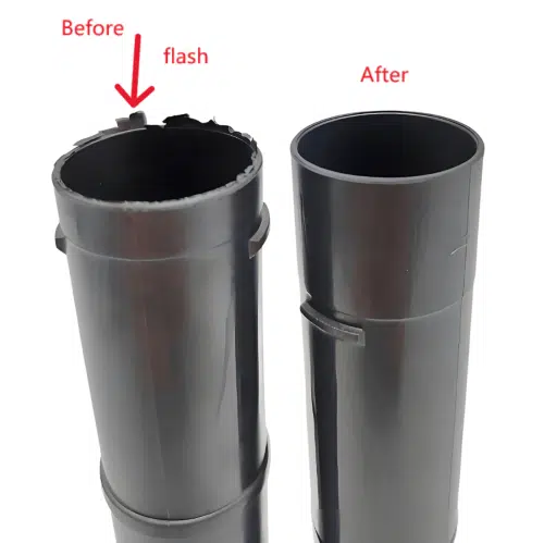
4. Weld Lines
Issue Explanation: Weak seams where melted resin streams converge. Weld lines form when two flow fronts meet and fail to bond completely.
Main Reasons Caused This:
• Low melt temperature or poor venting at merge points.
• Multiple gates causing flow front collisions.
• Cold mold temperatures accelerate solidification before bonding
Solutions To Mold:
• Relocate gates to minimize flow front meeting angles.
• Add overflow wells to capture cold material, add exhaust grooves or texturing at the core side of the mold surface.
Process Fixes:
• Raise mold temperature by 15–25°C to delay cooling.
• Increase melt temperature for better flow front fusion
• Optimize injection speed and pressure to maintain flow momentum
5. Flash (Burrs)
Feature Analysis: Excess plastic at mold parting lines. Specifically, flash occurs when material escapes the mold cavity along the parting surface during ejection.
Key Causes:
• The most common cause is worn mold components or misalignment.
• Additionally, excessive injection pressure overpowers the available clamp force.
• Another contributing factor is a damaged parting surface that allows material escape
Tooling Fixes:
• Replace worn mold components (e.g., inserts, slides).
• Add shear edges to parting lines (0.5–1mm wide).
• Repair or regrind the parting surface to ensure proper sealing
Parameter Changes:
• Calculate required clamp force: Projected area (cm²) × Material pressure (ton/cm²).
• Reduce the injection pressure, material temperature, holding time, and the holding pressure
• Adjust injection speed and pressure to stay within clamp capacity
6. Warping/Deformed Parts
Feature Analysis: Bent or twisted parts due to residual stress or long parts. This defect typically occurrs in parts with varying wall thickness or long flow paths.
Root Causes:
• Non-uniform cooling rates between thick and thin sections create internal stress.
• Premature ejection while parts are still soft allows deformation.
• Furthermore, excessive melt temperature creates high residual stress during cooling
Tooling Fixes:
• Use asymmetric cooling channels for balanced heat removal.
• Add ejector sleeves under high-stress areas.
• Optimize mold cavity design for uniform wall thickness
Process Refinement:
• Gradually cool mold: Start at 60°C, reduce by 10°C every 15 sec.
• Adjust cooling time to ensure complete solidification
• Monitor mold temperatures across all zones
7. Air Traps (Voids)
Description: Bubbles in transparent parts like PC or PMMA. Essentially, air traps occur when gas cannot escape the mold cavity during filling the mold.
Primary Factors:
• Poor venting at end-of-fill zones.
• Moisture in hygroscopic resins (e.g., nylon, PET).
• Insufficient vent depth on the parting surface
Mold Repair:
• Add vacuum-assisted venting systems.
• Polish runners to eliminate flow hesitation.
• Increase venting along the parting line and parting surface
Production Adjustments:
• Dry resins: Nylon (80°C/4hr), PC (120°C/4hr).
• Increase mold temperature, reduce injection speed and pressure.
• Adjust injection speed and pressure to allow gas escape
8. Burn Marks
Defect Breakdown: Black/discolored streaks near vents or thick sections. Burn marks are caused by trapped air compressing and igniting during filling the mold.
Primary Factors:
• Overheated resin due to excessive shear or trapped air.
• Poor venting at the parting surface
• High injection speed and pressure causing air compression
Mold Repair:
• Similarly, widen vents to 0.03–0.05mm for trapped gas escape.
• Avoid sharp corners in runner systems.
• Clean vent channels on the parting surface regularly.
Production Adjustments:
• Reduce screw rotation speed by 20–30%.
• Reduce injection speed in final filling stage
• Lower melt temperature to prevent degradation
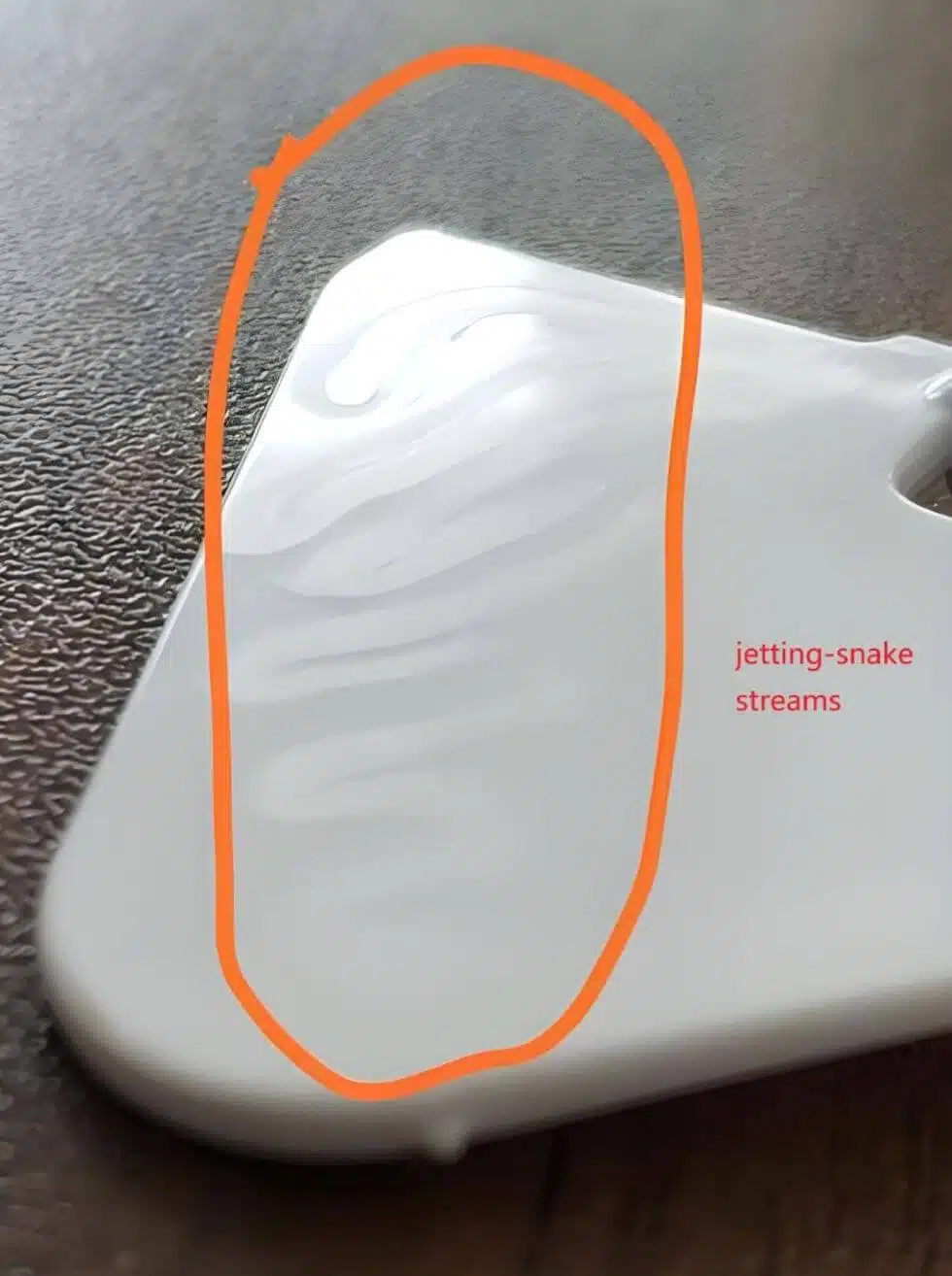
9. Jetting
Feature Analysis: Snake-like resin streams causing weak spots. Jetting occurs when material enters the mold cavity at high speed without contacting the walls.
Core Issues:
• High-speed resin injection through small gates.
• Mold cavity should be properly vented to prevent air traps
• Low melt temperature causing thick flow fronts
Tool Revisions:
• Switch to fan or tab gates to disperse flow.
• Relocate gate to direct flow against cavity wall
• Polish the mold cavity to reduce friction
Operational Tweaks:
• For instance, use a 2-stage injection profile: Slow initial fill, then fast.
• Adjust injection speed and pressure to promote wall contact.
• Increase injection speed gradually after initial filling

10. Splay Marks (Silver Streaks)
Defect Diagnosis: Silvery traces from moisture or degradation. These defects compromise quality injection molded parts.
Operational Tweaks:
• Dry resins: ABS (80°C/2hr), PET (150°C/4hr).
• Reduce melt temperature by 10–20°C.
• Adjust injection speed and pressure to minimize shear
11. Ejector Pin Marks
Overview: Stress whitening or surface damage. This issue is typically occurs when ejection force exceeds material strength.
Die Modifications:
• Increase ejector pin diameter by 10–15%.
• Use ejector sleeves for fragile parts.
• Make sure mold cavity surface for easier release
12. Delamination
Visual Identification: Flaking surface layers. Delamination prevents producing quality injection molded parts.
Critical Factors:
• Contaminated or incompatible materials.
• Excessive mold release agents.
• Low melt temperature causing poor layer bonding
Fixes:
• Purge barrels thoroughly between material changes.
• Clean mold cavity to remove release agent buildup
Material-Specific Shrinkage Rates
| Material | Shrinkage Rate (%) |
|---|---|
| PP | 1.50% |
| PP+10%GF | 0.7~1% |
| PP+30%GF | 0.4~0.7% |
| PP+T20% | 1.0~1.5% |
| ABS | 0.50% |
| PS | 0.50% |
| PC | 0.50% |
| HIPS | 0.50% |
| PC+ABS | 0.50% |
| POM | 2% |
| HDPE | 1.50% |
| PA | 1.20% |
| PMMA | 0.50% |
| PBT+30%GF | 0.50% |
Defect Troubleshooting Quick Reference Table
| Defect | Primary Cause | Quick Fix | Mold Modification |
|---|---|---|---|
| Short shot | Low pressure | Increase injection pressure | Widen gates |
| Sink marks | Uneven cooling | Extend holding time | Add conformal cooling |
| Weld lines | Low melt temp | Raise mold temperatures | Add overflow wells |
| Flash | Excessive pressure | Reduce injection pressure | Replace worn components |
| Warping | Non-uniform cooling | Gradual cooling profile | Asymmetric cooling channels |
| Air Traps | Poor venting | Increase mold temperatures | Add vacuum venting |
| Burn marks | Trapped air | Reduce screw speed | Widen vents |
| Jetting | High speed | 2-stage injection profile | Switch to fan gates |
Pro Tips to Prevent Injection Molding Defects
1. Simulate First: Use Moldflow simulation to predict filling patterns. And identify potential defects in injection molding and their troubleshooting needs before steel is cut.
2. Document Settings: Record pressure, temperature, and cycle times for repeatability. This data is essential for future mold troubleshooting reference.
3. Maintenance: Clean molds weekly with ultrasonic baths to prevent residue buildup that causes surface defects. Pay special attention to the parting surface.
4. Material Preparation: Always dry hygroscopic resins according to specifications to reduce sink marks in plastic parts and prevent splay marks. Monitor melt temperature closely.
5. Process Monitoring: Use cavity pressure sensors to detect variations early and adjust parameters to how to fix injection molding defects in real-time.
6. Ventilation Check: Regularly inspect the parting line and parting surface for blockage that can cause burn marks and air traps.
7. Flow Analysis: Study how flow fronts meet in your mold cavity to predict weld lines and adjust gate locations accordingly
Conclusion
This comprehensive guide to defects in injection molding and their troubleshooting provides the knowledge you need to identify root causes and apply effective remedies. Understanding the injection molding process, maintaining proper melt temperature, optimizing cooling time, and ensuring clean parting surfaces are key to producing quality injection molded parts.
By addressing these defects early, you reduce scrap rates by up to 30% (Source: Plastics Today). Need tailored solutions? Contact our engineers for mold optimization!
FAQs
Q: Can I get this guide as a printable reference?
A: Yes! We’ve prepared a complete Injection Molding Defects Causes and Remedies PDF for you. Simply click the download link at the top of this article to get your portable, printable reference guide. For a customized troubleshooting guide tailored to your specific parts and materials, contact our engineering team for personalized assistance.
Q: How can I reduce sink marks in plastic parts?
A: First and foremost increase holding pressure and time to pack more material into thick sections.
Secondly, optimize cooling time to ensure complete solidification before ejection.
Third, redesign ribs to be ≤60% of wall thickness to prevent excessive material accumulation.
Additionally, use conformal cooling in the mold cavity for uniform heat dissipation across all areas.
Finally, monitor melt temperature and mold temperatures closely throughout the production cycle.
Q: What causes burn marks in injection molding?
A:Generally speaking, burn marks typically occur when air trapped in the mold cavity compresses and ignites during filling the mold. This can be prevented by improving venting along the parting surface, reducing injection speed and pressure, and lowering melt temperature.
Q: What is the ideal cooling time for quality injection molded parts?
A: Cooling time depends on wall thickness, material, and mold temperatures. As a rule, thicker sections require longer cooling time to prevent sink marks and warping. Use mold temperature sensors to optimize cooling time for each molded part.


